Why Choose a Pneumatic Punching Machine?
Choosing a Pneumatic Punching Machine begins with a practical question: what must the machine produce every day?
In busy fabrication workshops, operators often need clean holes, repeatable shapes, and steady production. A pneumatic system uses compressed air to drive the punching action. This design can provide fast cycling, simple controls, and consistent force for suitable materials. It may also require less complex maintenance than some hydraulic alternatives. However, performance depends on air pressure, die condition, material thickness, and correct machine setup.
Small details matter. A dull punch can leave rough edges. Moisture in the air line can damage valves and reduce reliability. Poor alignment may create uneven holes or shorten tool life. These problems are not dramatic at first. They become expensive later.
Taiichi Ohno, Toyota’s respected production engineer, said, “Without standards, there can be no improvement.” That principle remains valuable when evaluating a Pneumatic Punching Machine. Operators should record cycle times, reject rates, air consumption, and maintenance intervals. Real workshop data is more trustworthy than a supplier’s broad promise.
Safety also deserves attention. Proper guarding, emergency stops, stable workholding, and operator training should be verified before production begins. A pneumatic machine is not automatically the best choice for every application. Thick steel, unusual shapes, or high-force requirements may demand another technology.
Still, for repetitive punching in light and medium materials, it can offer a practical balance of speed, control, and operating cost. The decision becomes stronger when equipment capability matches actual production needs, not optimistic assumptions.
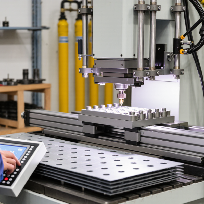
Pneumatic Punching Machines: Components and Operating Principles
A pneumatic punching machine converts compressed air into controlled mechanical force. Its main components include an air filter, pressure regulator, directional valve, cylinder, piston rod, punch, die, frame, and control pedal. The filter removes water and particles. The regulator sets working pressure. The valve then directs air into the cylinder, pushing the piston rod downward. The punch cuts or forms material against the die. When the valve reverses, a spring or opposing air chamber returns the piston.
Force depends on pressure and piston area. At 6 bar, a cylinder with a 100 cm² piston produces about 6,000 newtons of theoretical force. Friction, leakage, and alignment reduce the actual result. A practical operator should inspect the punch edge, die clearance, and hose connections before each shift. Small air leaks can sound harmless. They are not.
The U.S. Department of Energy’s Improving Compressed Air System Performance report states that compressed air may account for roughly 10% of industrial electricity use. It also notes that system leaks can waste 20–30% of compressor output. This matters when choosing pneumatic equipment. Pneumatic machines offer fast cycling, clean operation, and simple force control, especially for repetitive light or medium-duty work. However, they are not universally efficient. Noise, moisture, pressure fluctuations, and compressor energy demand require attention. ISO 12100 risk-assessment principles also support guarding, reliable controls, and safe access around the punch and die.
Safety Requirements Under ISO 12100 and OSHA Machine-Guarding Rules
Why Choose a Pneumatic Punching Machine?
Safety Requirements Under ISO 12100 and OSHA Machine-Guarding Rules
A pneumatic punching machine can deliver repeatable force with less manual effort. However, speed does not equal safety. ISO 12100 requires a documented risk assessment before production begins. Assess crushing, shearing, ejection, noise, unexpected cycling, and maintenance access. The operator’s hand should never reach the point of operation during a normal stroke. A fixed guard, interlocked guard, or presence-sensing device may be appropriate. The choice depends on the machine layout and risk evaluation.
OSHA’s Machine Guarding Safety and Health Topics page reports about 18,000 machinery-related amputations and 800 deaths annually in the United States. That figure makes guarding more than a design preference. OSHA 29 CFR 1910.212 requires protection from points of operation, rotating parts, and flying chips. Applicable press requirements may also involve two-hand controls, safeguarding distances, and inspection records.
Use lockout/tagout under 29 CFR 1910.147 during die changes and servicing. Test the emergency stop, inspect hoses, and verify air pressure before each shift. Small leaks matter.
A guard can still fail if workers bypass it for convenience. In real workshops, production pressure often exposes that weakness.
Supervisors should record near misses, retrain operators, and review controls after every process change. Industry guidance is useful, but the machine’s actual hazards must control the final decision.
Air Consumption, Maintenance Intervals, and Cost per Punched Part
Why Choose a Pneumatic Punching Machine?
Air Consumption, Maintenance Intervals, and Cost per Punched Part
Compressed air can seem inexpensive, but every stroke adds compressor load and energy use. Measure actual flow at working pressure, rather than trusting a catalog maximum. A calibrated flow meter and cycle counter provide stronger evidence. A short test run gives better evidence.
For example, a machine using 0.8 cubic meters per minute at 30 parts per minute consumes about 0.027 cubic meters per punched part. Multiply that figure by your local compressed-air cost. Then include electricity, filters, drying, and leakage. The estimate is never perfect. A small leak near a fitting can quietly raise costs for weeks. Keep a simple log of pressure, flow, output, and rejected parts.
Maintenance intervals should follow cycle count and air quality. Drain moisture daily, inspect hoses and fittings weekly, and check lubrication according to the equipment manual. Replace worn seals when pressure drops, stroke speed changes, or noise increases. Cleaner air usually extends valve and cylinder life. However, over-lubrication can attract dust and create another problem. I would review the interval after the first month, because real production is rarely as clean as a trial test. Cost per part also changes when stoppages, setup time, and unplanned repairs enter the calculation.
Why Choose a Pneumatic Punching Machine? - Air Consumption, Maintenance Intervals, and Cost per Punched Part
Values represent typical engineering ranges for properly sized pneumatic punching equipment operating in a clean industrial environment. Actual performance should be verified against the machine's cylinder volume, cycle profile, tooling load, and compressed-air system capacity.
